Back to the Hippodrome - An Epic Light Show

by NSL
A few years ago we were approached by Noah Larmz for a light show for one of our favorite shows Fantastic Planet. This spawned Noah Larmz Research & Development, eventually we renamed ourselves North Street Labs a more fitting name. We worked hard designing, prototyping and building our first large scale light show sign in just under 2 months - the Fantastic Planet Sign, a wonder of soldering, programming, in-house etched circuits, and amazing team work from all our friends! After a few years having fun and creating things here at NSL, we were approached by a newly formed and renovated venue the RVA Hippodrome to commission another light show - in short time and to be totally designed by us! We were jumping with joy to be involved in yet the creation of another party of epic proportions.
We planned an idea and sketched it with Google Sketchup, they liked the idea and we ran with it! We started buying materials, proving concepts, talking to Chinese and US suppliers. It shouldn't be surprising that the USA is often cheaper for unfinished goods unless you are buying in bulk. Always talk to the local companies, they will often cut you a break if you are a bunch of locals working on a public project with little to no money to be made.
After countless hours of work, lacking sleep because of the Red Bull Creation 2012 competition, and general craziness - we finished the build in time before the bands did their sound testing last week on Sunday August 5th. And the show was a success! Everyone had a great time, Richmond discovered a brand new venue of beautiful design and new technology up there with some of the best we've ever seen. here is a clip we made of the show:
Lots of pics of the show:
 |
 |
 |
 |
 |
 |
 |
 |
 |
 |
 |
 |
Expect us back in October for another crazier Halloween party!

About the build:
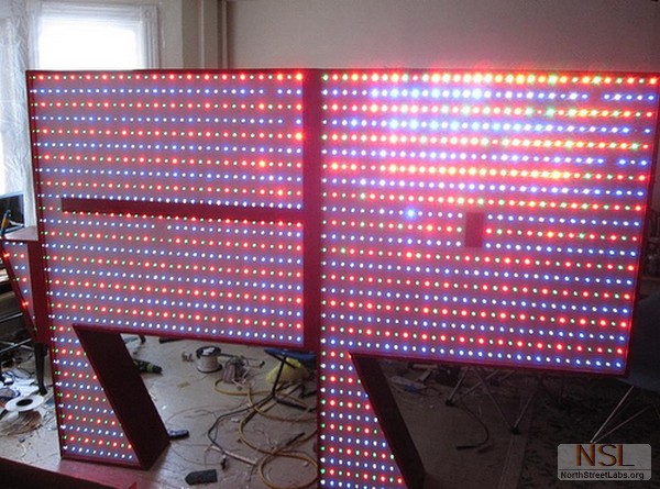
With our previous experience with subwoofer boxes, CNC machining and furniture creation, we designed simple yet elegant light boxes to help distribute the over 750 RGB LEDs that make up this display. Nine full sheets of 1/2" birch plywood and 3 sheets of 1/4" hardboard make up the wooden boxes, the front panels are the only things CNC'd on these boxes.
 |
 |
 |
 |
 |
 |
 |
 |
We ordered 44 LED/M 24IC/M LPD8806 strips from CLEN LED through Alibaba, 16 meters of them! With our budget we couldn't afford to make the show awesome enough at Adafruit's prices. Using Alibaba is extremely risky and we were hesitant, but Jack Huang an English Tourism Major working for CLEN LED was a great translator and even knew his LEDs well! You can contact Jack Huang for help here: Mr. Huang. It was a nervous order with only money order or direct bank transfer as the payment options. He assured me everything was well, and he even had them shipped to us in less than a week! They are a good company, the good guys from China, I trust them. They even included a string of 4LED/pixel squares we used in our SIMON game because I accidentally overpaid them ~$20. When you contact them, be frank, courteous and let them know what you are doing, they might actually be interested in your hackerspace project!
 |
 |
 |
 |
 |
 |
 |
 |
Each box consists of an 5v 5amp power supply from ebay, 3 have since failed. Do not buy the cheaper ones from china, or even the USA reseller as we did (Also they said 5v 4a on the inside! What a rip-off.) From now on we only buy nice power supplies. There is an Arduino UNO Rev 1 in every box, connected to an RS485 MAX485 breakout board. They receive data from the MASTER by a serially connected RS485 bus. And finally 86 RGB LEDs and 43 LPD8806 ICs in each box, a total of 688 RGB LEDs!
An Arduino MEGA 2560 serves as the brain of the system controlling what each light box does, it is connected to several SparkFun EL Escundo Dos boards, an MSGEQ7 7-band equalizer, an adjustable electret microphone, an RS485 differential transceiver, and a 240w 12v power supply that wasn't nearly as bad as those pesky 5v 5a ones.
 |
 |
 |
 |
There is an impressive amount of EL wire too, White, Blue and Red EL Wire total over 300 feet! Between several 12v high output inverters and the EL Escundo Dos boards there is stimulated lightning and strobing lighting towers! The EL wire is attached to "lightning towers" which are actually three Lightning Arrestors welded together to a 1" square tube of steel, which bolt directly to the stage. All the lightning EL Wire is strung from the main controller, up the back of the lightning towers and towards the ceiling/wall/speakers with the help of staples/Gaff tape. The effect is hard to capture but beautiful in person.
 |
 |
 |
 |
We had problems finding a good diffusion that wouldn't lose too much light. Baking sheet looked the most promising (especially for the cost - $5 would provide us all we needed) But it wasn't as blindingly bright, looked more like a nice multicolored lamp. We wanted to use a particular ROSCO Gel used in theatrical lighting, but that would cost well over $200, we settled on Privacy Window film two layers thick to achieve the best diffusion. The light is bright, and diffused, but it is NOT dimmed by any means, like any tracing paper/baking sheet caused. We wanted to paint/aluminum foil the interior, but time was against us. For those paying too much attention, one box was not used because of technical issues from a power supply explosion. Again, a nice power supply is EXTREMELY IMPORTANT!
 |
 |
 |
 |
The wood was glued, clamped, and pin-nailed over a couple of days. Then slowly the circuits were assembled, wired up, tested. A few problems were found and painfully fixed, pro tip: Make sure soldering on the strips work before removing the adhesive backing protection. Cold soldering joints are easy to do when you are trying not to overheat these strips, we had a few of these. Don't do this, it's irritating to fix if you've already installed them.
Here's a small video we made when we realized it actually worked!
Several sub programs were written, combined and reprogrammed to work again. We used the PS2X and EasyTransfer library from Bill Porter, and the LPD8806 library from Adafruit. The PSX controller is one of our favorites to use, there are many buttons to choose from, joysticks to manipulate and more if you dive deep enough. You can get our current working code here. This code relies on a PS2 controller connected to an Arduino and uses TX to communicate to an Arduino on the RX line, as well as using the hardware SPI on the Arduino UNO for controlling the LPD8806 strips. We needed that extra distance, so we used MAX485 transceivers to allow hundreds of feet between connections. If you have any questions, shoot us an email below.
Right now the code above consists of Smart Boxes, but a dumb command center. Below is the code we originally developed for data sending upon the RS485 network, it assumes a smart controller and dumb light towers, all the light towers should know how to do is turn 8 pixels of 24 bit RGB data into 24 bits of data for the 86 RGB LEDs. This is a simple way to control the 16,512 bits of 0s and 1s that make up a single "frame" of the entire light show. However my code below refuses to work, and I settled on the crappy code linked above. If you think you have a tip or suggestion for what is wrong with my code below, shoot me an email:[email protected]
NON-WORKING CODE BELOW!
MASTER:
#include <EasyTransfer.h> PS2X ps2x; // create PS2 Controller Class //right now, the library does NOT support hot pluggable controllers, meaning //create object struct SEND_DATA_STRUCTURE{ //give a name to the group of data void setup(){ void loop(){ for(int i = 0; i< 24; i++){ }
delay(300); for(int i = 0; i< 24; i++){ } ET.sendData(); |
SLAVE:
#include <EasyTransfer.h> // Example to control LPD8806-based RGB LED Modules in a strip /*****************************************************************************/ // Choose which 2 pins you will use for output. // Set the first variable to the NUMBER of pixels. 32 = 32 pixels in a row int NumLED=86; //BEGIN EASYTRANSFER //give a name to the group of data void setup(){ // Update the strip, to start they are all 'off' void loop(){ // Create a 24 bit color value from R,G,B |
